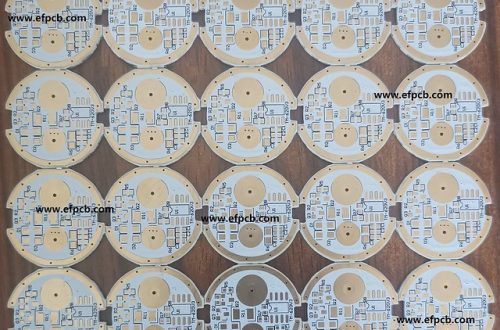
RF and Amplifier PCB
RF and Amplifier PCB
An amplifier PCB must have a high ground plane to avoid coupling with other signals. Also, RF transmission lines may require a ground space above and below them.
Choosing the best PCB material is vital to the overall performance of an amplifier. The ideal choice will have a consistent dielectric constant and CTE across dimensions and with temperature.
Material Selection
Choosing the right material for an RF board is arguably the most critical step in the whole PCB design process. It’s from this choice that many of the other RF and Amplifier PCB key factors that influence performance, manufacturability and cost will stem.
Standard FR-4 (flame retardant level 4), for example, is cheap and easy to work with, but it has a high dissipation factor and worse loss tangent than materials designed for use at higher frequencies. It also suffers from impedance variations along the traces as the frequency rises. This can lead to distortion and signal degradation.
Another factor to consider is the environment in which the RF board will operate. Moisture absorption is important here. The moisture content that the material can withstand needs to be taken into account as well as the CTE, or co-efficient of thermal expansion, which will affect how the board handles temperature stresses like soldering.
PTFE, ceramic filled PTFE and woven glass are typical materials used in RF PCBs. These materials have low lamination and re-melt temperatures, meaning that they can be used for the core layers of an RF circuit. However, for the outer layer a material that can be bonded easily to copper with low melting points is preferred. This is because the board will undergo a lot of thermal stress during assembly and operation.
Layout Design
All PCB designs must consider factors such as size and mechanical fit, but RF systems carry some unique considerations. These can include what protocols the system will be running, how much power it will draw, and what frequencies it will operate at.
One of the most important steps in RF design is choosing the type of circuit trace to use. TI has several reference designs that recommend different trace geometries for specific applications. Choosing the right trace geometry will impact signal timing, impedance, and noise coupling.
RF design also requires careful routing of interconnects. Keeping these short is critical to minimizing EMI (Electromagnetic Interference) and keeping signals within their bandwidth. It’s also essential to eliminate large loops of ground-return traces, which can radiate electromagnetic energy and interfere with the signal.
Another critical decision is whether to use a microstrip or stripline. Both are effective in reducing skin effect loss, but microstrips have lower losses and are easier to route than striplines. Whether to use one or the other will depend on the application, board stack-up, and the dielectric constant and loss tangent of the PCB’s dielectric layer.
Lastly, the placement of the component’s ground plane is key to good RF performance. It’s best to place this on the component layer directly under the IC. Adding signal layers between the bias and ground plane creates a return current path that can cause EMI interference.
Stackup
When it comes to making a quality electronic product, PCBs are a crucial component. This is because the PCB stack up design determines how well an electrical product functions and performs. In order to come up with a good PCB stack up design, there are several factors that need to be taken into consideration. This includes the materials to be used and the number of layers in a PCB.
Another factor to consider when designing a RF and amplifier PCB is the material for the board’s layers. Various options are available, ranging from standard FR-4 laminates to advanced thermoset-resin dielectric materials. The best choice will depend on the specific application and the desired performance characteristics of the final device.
When calculating the tolerance stack up, it is important to keep in mind that there are different types of tolerance analysis models. These include worst-case and statistical tolerance analyses. Worst-case tolerance analysis will calculate the maximum possible variation for a given measurement gap, while statistical tolerance stackup calculations will take into account how each dimension-chain affects the assembly measurement. The latter approach will help engineers and designers to find the optimum assembly tolerance requirements that are compatible with manufacturing and performance goals.
Via Holes
The size of the via holes plays a crucial role in the impedance of RF signal lines. The larger the diameter of the hole, the lower the trace impedance because there is more metal area to carry current compared to a smaller hole. Ideally, the diameter of the via should be consistent with the width of the trace to minimize transition RF and Amplifier PCB Supplier inductance and capacitance. However, it’s critical to consider the CTE (coefficient of thermal expansion) of the copper used to make these connections. A high CTE could result in the formation of weak interconnections that are susceptible to cracking during reflow soldering.
It’s also important to consider the placement of RF signal lines on multilayered PCBs. As much as possible, they should be routed away from digital or analog circuits to prevent coupling between them. They should also be kept short and related to a ground plane for better signal integrity. If RF signals are required to cross each other, it’s best to use a coplanar waveguide to ensure strong isolation between them.
This medium consists of a center conductor with ground planes on both sides and below it. This helps to reduce the inductance of the traces because the DC and RF return currents will be shorted to the ground planes. However, it’s still necessary to place a row of ground vias in the bottom of the component layer as well as on each side of the center conductor.
